URSC Indian Space Research Organization (ISRO) Rocker-Bogie Rover
I contributed to the URSC Rover project, an initiative by ISRO, which was assigned to the I3D Lab at the Indian Institute of Science. My role involved developing algorithms and selecting sensing elements to enable efficient movement of the rover. The project also aimed to autonomously operate a 5-DOF manipulator for object pick-up using cameras and object detection models. Additionally, I explored motion planning algorithms for both the rover and the manipulator to enhance operational efficiency.
Mechanism Design
Our rover employs a Rocker Bogie mechanism with six wheels to enhance stability and adaptability over rough terrain. The mechanism allows for continuous ground contact with all wheels, ensuring optimal traction and maneuverability.
.png)
Drive Electronics Design
The drive system consists of four servos and six DC motors that control the rover's angular and linear speed. These servos and motors are connected to an electronic control unit (Arduino MEGA) that processes input from the navigation system and translates it into precise movements. We are powering a pair of DC motors through a single battery source of capacity 2200 mAh with 12V supply. Similarly, robotic arm and servos are also powered with two different such batteries. Hence we utilised a 5 channel relay switch to power the kill switch as shown below.
.png)
Design Calculations
The design calculations for the drive system include torque requirements, power consumption, and load distribution. Detailed calculations are as follows:
Power Consumption
First, we sum up the power consumption of all components:
6 Drivers: Minimal (we'll assume this to be negligible for now)
6 Motors: 540W Arduino: Minimal (we'll assume this to be negligible for now)
4 Servos: 106.4W (assumed for highload case)
Lidar: 2.5W
Robotic Arm: 60W (assumed for highload case)
Total Power Consumption = 540 𝑊 + 106.4 𝑊 + 2.5 𝑊 + 60 𝑊
Total Power Consumption = 708.9 𝑊
Battery Capacity
Total Battery Capacity = 5 × 2200 mAh × 12 V
Total Battery Capacity = 132 Wh
Battery Life Calculation To find the duration the battery will last, we divide the total battery capacity
by the total power consumption:
Battery Life = Total Battery Capacity/Total Power Consumption
Battery Life = 132 Wh/708.9 W
Battery Life ≈ 0.186 hours
Battery Life≈0.186hours
Converting this into minutes: 0.186 hours × 60 minutes/hour ≈ 11.16 minutes
0.186hours×60minutes/hour≈11.16minutes
Conclusion: Under the given high load conditions, the batteries will last approximately 11.16 minutes. This analysis assumes that the power consumption is constant and does not account for any power management or efficiency improvements that might extend battery life. However under average load conditions we observed the rover worked for about 25-30 minutes without a break while navigating outdoors and indoors.
Torque Calculation:
To determine the motor torque required for the rover, we focus on the static load for the six wheels of the rover. The calculation considers the scenario where the rover needs to climb a slope of 15 degrees.
Assumptions
- The rover is in equilibrium while climbing the slope.
- The weight of the rover is evenly distributed across the six wheels.
- Static friction is the primary force preventing slipping.
- The rover's weight and friction are the only forces considered for torque calculation.
Variables
- (m): Mass of the rover = 9 kg
- (g): Acceleration due to gravity = 9.81 m/s²
- (µ): Coefficient of friction = 0.85
- (r): Radius of the wheel = 0.0625 m
- (θ): Angle of the slope = 15°
Forces Acting on the Rover
- Normal Force (N): N = mg cos θ
- Frictional Force (f_r): f_r = μN = μmg cos θ
- Parallel Component of Weight: mg sin θ
Equilirium condition
For the rover to remain stationary on the slope:
mg sin θ - μ mg cos θ + F = 0
Since F is the force provided by the motors, we have:
mg sin θ - μ mg cos θ + (6τ / r) = 0
Solving for τ (torque per wheel):
mg sin θ - μ mg cos θ + (6τ / r) = 0
τ = (r (μmg cos θ - mg sin θ)) / 6
Substituting the Values
𝜏 = (0.0625 (0.85 * 9 * 9.81 * cos 15° - 9 * 9.81 * sin 15°)) / 6
𝜏 = (0.0625 (74.865 - 22.89)) / 6
𝜏 = (0.0625 * 51.975) / 6
𝜏 ≈ 0.52 Nm
Thus, each motor must provide approximately 0.52 Nm of torque to keep the rover stationary on a 15° slope.
Weight of the Rover
The total weight distribution of the rover components is as follows:
- Motors (6): 1 kg
- Wheels (6): 1 kg
- Chassis: 3 kg
- Manipulator: 1.3 kg
- Battery: 1 kg
- Miscellaneous (Microprocessor and Sensors): 1.7 kg
Total Weight: 9 kg (conservative estimate).This weight distribution ensures the stability and mobility of the rover, allowing it to handle various terrains effectively while providing sufficient power for all functionalities.
.png)
Load Distribution
The load distribution analysis ensures that the rover's weight is evenly spread across its structure, allowing for optimal stability and maneuverability. This section details the weight distribution of the rover's components and how it impacts the overall load on each wheel.
.png)
Rover Dimensions
WheelBase-1: 737.75 mm
WheelBase-2: 704.73 mm
WheelBase-3: 580 mm
Wheel Diameter: 100 mm
Component Weights
Motors (6): 1 kg
Wheels (6): 1 kg
Chassis: 3 kg
Manipulator: 1.30 kg
Battery: 1 kg
Miscellaneous (Microprocessor and Sensors): 1.70 kg
Total Weight: 9 kg
To calculate the load distribution, we assume that the weight is evenly distributed across all six wheels. The rover's symmetrical design ensures that each wheel bears an equal portion of the total weight.
Total Weight on Each Wheel
Total weight=9kg
Weight per wheel = 9 kg/6 = 1.50 kg
Force on Each Wheel
The force exerted by the weight on each wheel can be calculated using the formula: 𝐹 = 𝑚 × 𝑔
Where: 𝐹 is the force 𝑚 is the mass (1.50 kg per wheel) 𝑔 is the acceleration due to
gravity (9.81 m/s²) 𝐹 = 1.50 kg × 9.81 m/s2 = 14.72 N F=1.50kg×9.81m/s2 =14.72N
Therefore, each wheel supports a force of 14.72 N. Distribution Analysis given the symmetrical placement of the components, the chassis, battery, and miscellaneous parts are centrally located, ensuring that the center of mass is well-balanced. The manipulator, mounted on top, is centrally aligned to avoid any toppling or imbalance.
Static Load Analysis: In the static condition, the load distribution remains uniform across all wheels. The mechanism aids in maintaining this distribution even when navigating uneven terrain. The analysis ensures that each motor can handle the torque requirements as calculated, providing sufficient force to overcome obstacles and maintain stability.
Conclusion: The load distribution analysis confirms that the rover's design maintains an even weight distribution across all wheels. Each wheel supports 14.72 N of force, ensuring stable operation and maneuverability. The central placement of heavier components like the chassis and battery, combined with the balanced manipulator placement, contributes to the overall stability of the rover.
Sensor Systems
The sensor suite includes two cameras for visual processing, LIDAR for point cloud generation, and IMUs for orientation and acceleration data. These sensors feed data into the ROS-Noetic system for real-time processing and decision-making
Software Requirements and Design Details
The rover designed for the Quals-1 Rover Functionality Round incorporates advanced autonomous
navigation capabilities structured around a sophisticated software and hardware integration,
defined by the following key identification requirements in terms of software and algorithms:
- Navigation Stack: ROS-Noetic move_base
- Mapping: Cartographer method for simultaneous localization and mapping (SLAM)
- Global Planning: A* algorithm
- Local Planning: Dynamic Window Approach (DWA)
To autonomously navigate the Rover, we used ROS specifically the ROS – Noetic Framework the steps
taken to autonomously move the Rover Are as follows:
Designing the ROVER and then Obtaining the URDF: Initially, we embarked on designing the
components of the Rover, with a keen emphasis on precisely positioning crucial sensing elements such
as Lidar and Camera. The accurate placement of these sensors is indispensable for enabling the Rover
to effectively perceive its surroundings. Later, we obtained the URDF (Unified Robot Description
Format) of the Rover. To accomplish this task, we utilized the URDF Plugin accessible on Fusion 360.
Importing the URDF into a Simulated Physics Engine: Our subsequent task involved importing the
created URDF file into a simulated physics engine known as Gazebo. This step was crucial for testing
the proper design of the Rover's joints. The image below depicts the URDF successfully imported into
the Gazebo physics engine.
.png)
Testing the Sensors: Prior to proceeding further, it was imperative to activate all the sensors and verify their functionality. To accomplish this, we employed RVIZ to assess the scan data from our Lidar and examined the latency of the camera image. The test results are illustrated below.
.png)
Launching Cartographer Localization: After confirming the correctness of the URDF, we proceeded to initiate Cartographer localization. This localization method requires connecting the Map frame to the Odom and base-link frames. To establish this connection, Cartographer utilizes a configuration file, with the Lidar frame being the primary frame it searches for. Once the Lidar frame is detected, Cartographer localization is activated, enabling map building. It was crucial for the URDF to contain the Lidar link without any errors for this step to be successful. The image below displays the TF Tree, which signifies that the connection was established, and Cartographer is running smoothly. The TF Tree, short for Transformation Frame tree, delineates how each frame of the robot is interconnected. This information can be invaluable for debugging the environment later on. An advantage of using Cartographer localization is its resilience: even if odometry fails, SLAM (Simultaneous Localization and Mapping) continues to function, as the robot can determine its position solely based on Lidar data
.png)
Mapping the Environment: To initiate mapping, the Cartographer node requires a parameter called "occupancy grid," which must be set to True. Once activated, the Lidar and Odometry collaborate to generate a map using the occupancy grid technique. Manual teleoperation of the Rover is necessary for this process. To achieve teleoperation, we established a ROS serial connection linking the Raspberry Pi to the Arduino, which controls the motors and drivers. A custom script was developed to create a remote-control interface, utilizing the laptop's arrow keys to maneuver the Robot. The maximum linear velocity was set to 0.22m/sec, and the Rover can also execute turns. In the generated map, free spaces are represented by white pixels, while obstacles are depicted by black pixels. By repeatedly moving the Rover, the occupancy grid discerns between obstacles and free spaces. The image below illustrates the map being created using the occupancy grid method.
.png)
Autonomous Navigation: To commence autonomous navigation, the first step is to load the map. Subsequently, we launch the move base navigation stack, which comprises several parameters, including the global cost map, local cost map, footprint of the robot, global planner (utilizing A* algorithm for finding the shortest path to a goal), and local planner (employing DWA for smooth continuous motion). The global cost map utilizes the existing map to determine the optimal global path, but obstacles may be encountered in the local environment. For this, the DWA planner calculates a local path, which initially follows the global path until an obstacle is detected by the camera or Lidar.At that point, a slightly altered path is chosen to navigate around the obstacle before resuming the global path. Additionally, move base incorporates built-in recovery behaviours such as rotate recovery and oscillation recovery to maneuver away from obstacles. Should these built-in modes fail, we have developed a ROS-UNITY bridge. This bridge connects the Rover to a digital twin, allowing manual control of the Rover via Mixed Reality, essentially tele operating it within the digital twin environment. The below Image shows a snapshot when the rover is performing autonomous navigation
.png)
Tuning the Move Base Parameters: Following the successful launch of the navigation stack with move base, the subsequent task involves tuning the parameters. These parameters include the footprint and inflation radius, which delineate the area surrounding obstacles. Increasing the inflation radius results in a larger distance between the rover and obstacles. Other parameters include min and max velocity, as well as goal distance bias, which influences how closely the local plan adheres to the global cost map. By reducing the goal distance bias, the local plan deviates more from the global plan. Additionally, we can adjust parameters such as goal tolerance and yaw tolerance to meet specific requirements. Modifying these values ensures smooth rover operation when navigating towards the goal.
Specifications of Components
The rover utilizes the following COTS components:
- Servos: Orange OT5330M 7.4V 35.5kg.cm 180° Metal Gear Digital Servo Motor
- Camera: Logitech C615 Portable 1080P HD Webcam with Built-in Mic and Swivel Design
- LIDAR: YD Lidar X2
- IMUs: BNO055 9-DOF Absolute Orientation Sensor by Adafruit
- Control Units: Arduino Mega 2560 ATmega2560 MCU Rev3 A000067, Raspberry Pi 4 (4GB)
Navigation Algorithms
The navigation system employs a combination of A* for global path planning and the Dynamic Window Approach for local obstacle avoidance. These algorithms ensure efficient and safe navigation through complex environments.
Software Requirements and Design Details
Cartographer Localization: Cartographer localization refers to the process of using the Cartographer system for simultaneous localization and mapping (SLAM) in robotics. It involves generating accurate maps of environments in real-time while estimating the position and orientation of the robot within these maps. Cartographer achieves this by integrating data from multiple sensors, such as LIDAR, IMU, and odometry, and employing advanced algorithms for sensor fusion. This allows robots to navigate complex environments with precision and efficiency, making Cartographer a valuable tool for robotics research and applications. Cartographer can be used in both 2D and 3D Lidar’s even if the odometry fails SLAM can continue when we use Cartographer this is because the lidar’s data is used to localize the robots. It operates by creating small, optimized submaps through local SLAM techniques, then identifies overlaps in these maps (loop closures) to correct drift and integrates these submaps into a cohesive global map using a background pose graph optimization. This sophisticated process allows Cartographer to maintain real-time performance and accuracy, essential for autonomous navigation in dynamic settings.
A* Algorithm: The A* algorithm is a widely used pathfinding algorithm that efficiently finds the shortest path between two nodes in a graph. It employs a heuristic function to guide its search, prioritizing nodes with lower estimated costs. By systematically exploring the graph while considering both actual and estimated costs, A* strikes a balance between completeness and efficiency, making it ideal for applications such as route planning in maps, robotics, and video games.
DWA Local Planner: Dynamic Window Approach (DWA) Local Planners are key components in robot navigation systems, particularly in dynamic environments. These planners use a predictive model to assess potential future trajectories based on the robot's current velocity and surroundings. By considering both robot dynamics and obstacle avoidance, DWA planners aim to generate feasible and safe trajectories that allow the robot to reach its goal efficiently while avoiding collisions. This approach offers flexibility and adaptability, making it suitable for various robotic platforms and realworld scenarios, from mobile robots in warehouses to autonomous vehicles navigating city streets
.png)
Manipulator Sensor System
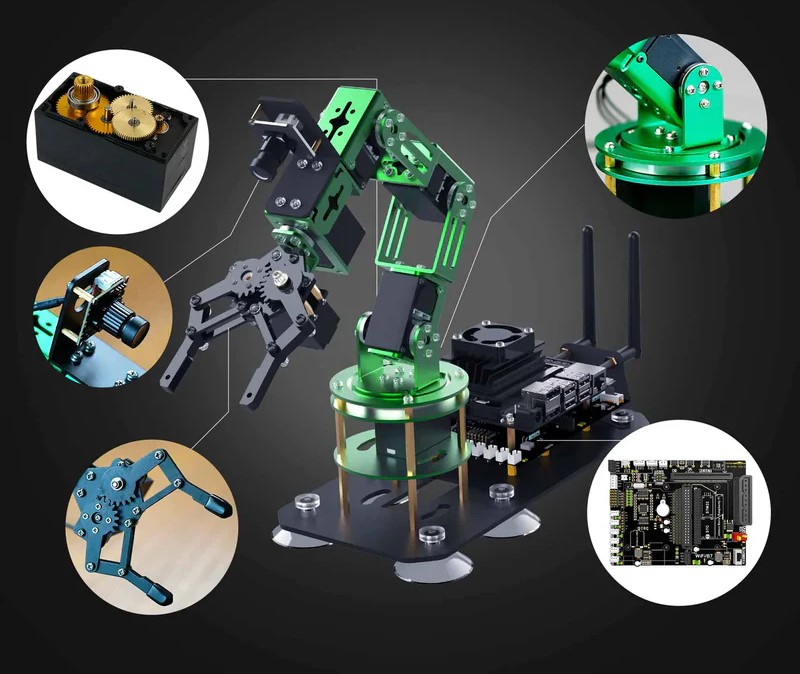
The arm is equipped with position encoders to ensure precise control and feedback during operation. Manipulator sensor system contains an internal camera mounted on the gripper and an external camera mounted on the base. The internal camera moves along with the gripper. But we use only the external camera for object detection. See following figure for the sensor configuration.
Software Requirements and Design Details
The manipulator's control software integrates with the ROS framework, allowing for coordinated
tasks with the navigation system. Key components include:
- Pick and Place Algorithm: We use a custom IK solver
- Control Interface: ROS action servers and clients
- Object detection and pose estimation: YOLO World, FastSAM, Homography mapping
- Hand-eye Calibration – OpenCV Library
The pose of the object is estimated w.r.t to the external camera. We need to transform the object
pose w.r.t manipulator base inorder to pick the object. Therefore, the transformation between
external camera and manipulator base is important.
.png)
Where ⬚𝑐𝑖𝑇𝐴, ⬚𝑐𝑒𝑇𝐴are the poses of the aruco marker w.r.t internal and external cameras.⬚𝑔𝑇𝑐𝑖is found by hand-eye-calibration in eye-in-hand configuration
Pose Estimation
We assume that objects are in ground plane. Using homography we can project the bottom of the detected 2d bounding box to the ground plane. Add z=0 to the the middle of the bottom segment. Then use ⬚𝑐𝑒𝑇𝐴 camera matrix to get the pose w.r.t to external camera. Then again apply ⬚𝑏𝑇𝑐𝑒 to get the pose of the object w.r.t the base of the manipulator.
Manipulator Inverse Kinematics
We use the manipulator IK as discussed in the IK section to find the configuration of the robot at the picking configuration.
.png)
- It’s a 5 dof manipulator. We use a custom IK to find the joint angles corresponding to the target
location x,y,z.
- The input to the IK solver is (x, y, z,𝜙 ,𝜃4). 𝜙 is the angle that end effector makes with normal to the
ground plane and 𝜃4 is angle of the fingers.
- 𝜙 Is calculated based on the distance of the target from base. In our implementation it ranges from
0 (nearby target) to 60 degrees.
- 𝜃4 Is calcuated based the orientation of the object.
- Since 𝑙1, 𝑙2 𝑎𝑛𝑑 𝑙3 are in the same plane we can solve the joint angles 𝜃1, 𝜃2 considering new target
location at the end of 𝑙2.
.png)
.png)
These calculations are in +ve x and +ve y quadrant. The sign and offsets change in different quadrants
Object Detection Using YOLO-World
YOLO-World is a deep learning model that takes input frame and vocabulary embeddings and outputs a set of bounding boxes of detected objects. The figure shows the sample output.
.png)
Homography for Pose Estimation
Homography is a transformation between two planes. Since the objects are in the ground plane we transform image coordinates of bottom segment of bounding boxes to get the coordinates on the ground plane.
Crater Detection from Pseudo-top View
The left side shows the camera view and right side shows the pseudo-top view using homography. On the pseudo-top view. We can use Hough circle algorithm or any object detector (eg: YOLO-world with vocab. Embeddings corresponding to circular objects) to detect the craters.
.png)
Communication
Explanation:
WiFi Router: Connects to the PC and onboard RPi via WiFi.
PC: Communicates with the onboard RPi via WiFi using ROS-interface.
Onboard RPi: Connects to the Arduino using ROS-Serial for communication.
Onboard Arduino: Interfaces with the onboard RPi through ROS-Serial.
Key: Solid Line: Represents WiFi connections.
Dashed Line: Represents ROS-Serial connection.
.png)
RF Design Calculations
The rover's communication system utilizes standard ROS-Noetic communication protocols to transmit and receive data between the rover and the control station (PC). This setup ensures reliable and low-latency communication under various conditions, leveraging established ROS communication frameworks.
- Frequency Selection: The frequency selection is based on standard Wi-Fi frequencies (2.4 GHz or 5
GHz) used by the ROS-Noetic communication framework. These frequencies are chosen for their
widespread availability and compatibility with existing hardware.
- Range Calculation: The range of communication is determined by the Wi-Fi module used in the
system. Typical Wi-Fi modules have an effective range of up to 100 meters in open areas, which is
sufficient for the operational needs of the rover.
- Interference Analysis: Interference mitigation is handled by using standard Wi-Fi protocols that
include automatic channel selection and error correction techniques to minimize data loss and
communication delays.
Software Requirements and Design Details
The communication software is built on the ROS-Noetic framework, which facilitates seamless data transfer between the rover and the control station. Key features include:
- Protocol: ROS topics and services are used for communication. The rover publishes sensor data to
specific topics and subscribes to command topics from the control station.
- Error Handling: ROS inherently supports error detection and correction through message
acknowledgment and retransmission mechanisms. Additionally, ROS nodes can implement custom
error handling routines to manage communication failures and ensure robust data transfer.
Mobility Test
- Terrain Adaptability: We observed that rover is capable of moving over a ramp with slope of 15 degrees. It was also mentioned in the video demonstration as shown.
.png)
Mapping Accuracy
The maps that were generated were observed to have a resolution of 4 cm per pixel. We benchmarked the mapping with methods like FASTSLAM 2.0, HECTOR Slam and Cartographer based mapping. We observed that, cartographer gives the best accuracy and localization compared to the other methods.
Obstacle Avoidance Accuracy
As it can be observed in the below diagram, the obstacles which are at a height of 30 cms, were highlighted in the locl costmap of the rover and the rover is able to navigate autonomously to the destined goal via the global path generated
.png)
Manipulator Tests
- Pick and Place Accuracy: We observed that manipulator is capable of pick and placing the samples when presented infront of it. The below image represents the autonomous pick and place capability of the manipulator.
.png)
Conclusion
In conclusion, we tested various algorithms, including A*, Dijkstra, and a hybrid A*-Dijkstra algorithm for global path planning, ultimately determining that the hybrid approach was the most effective. For local path planning, we evaluated DWA, collision cone, and a hybrid of the two, concluding that DWA was the best option. For SLAM, we selected Cartographer over Gmapping and used it to navigate the rover, preferring it to AMCL for autonomous localization using point cloud stream localization. We custom-built kinematics for the 5-DOF articulated arm and controlled it via an HTTP web server message, which was computationally less intensive than using MoveIt. We employed YOLO models for object detection and pick-up, while a pseudo top view was generated to detect and avoid craters. Additionally, a ROS-UNITY Bridge was created to maneuver the digital twin of the rover in scenarios where onboard recovery systems fail. The onboard recovery systems we implemented included rotate recovery behavior and costmap clearing. These findings were provided to the Indian Space Research Organization (ISRO) for implementation on the real rovers they planned to build at the URSC center.
References
- Sariya (Aug 2020). Design of Rocker Bogie Mechanism, in International Research Journal of Engineering and Technology (IRJET).
- Castañeda, E. A., Asmat, A. D., Pejerrey, M. J., Jara, C. M., Cabrejos, L. G., & Cornejo, J. (2022, July). Generative Design and DEM-FEA Simulations for Optimization and Validation of a Bio-Inspired Airless Tire-Wheel System for Land-Based Space Planetary Exploration Robot. In 2022 International Conference on Advanced Robotics and Mechatronics (ICARM) (pp. 929-936). IEEE.
- Manuelli, L., Gao, W., Florence, P., & Tedrake, R. (2019, October). KPAM: Keypoint Affordances for Category-Level Robotic Manipulation. In The International Symposium of Robotics Research (pp. 132-157). Cham: Springer International Publishing.
- Kaiming He, Georgia Gkioxari, Piotr Dollár, and Ross Girshick. Mask R-CNN. In Proceedings of the IEEE International Conference on Computer Vision, pages 2961–2969, 2017.
- Xiao Sun, Bin Xiao, Fangyin Wei, Shuang Liang, and Yichen Wei. Integral Human Pose Regression. In Proceedings of the European Conference on Computer Vision (ECCV), pages 529–545, 2018.
- P. Marion, P. R. Florence, L. Manuelli, and R. Tedrake. Label Fusion: A Pipeline for Generating Ground Truth Labels for Real RGBD Data of Cluttered Scenes. In 2018 IEEE International Conference on Robotics and Automation (ICRA), pages 3235–3242, May 2018.
- Marcus Gualtieri, Andreas Ten Pas, Kate Saenko, and Robert Platt. High Precision Grasp Pose Detection in Dense Clutter. In 2016 IEEE/RSJ International Conference on Intelligent Robots and Systems (IROS), pages 598–605. IEEE, 2016.
- Mars Climate Orbiter - NASA Science (no date). NASA. Available at: https://science.nasa.gov/mission/mars-climate-orbiter/ (Accessed: 14 January 2024).
- Zhang, B., Li, G., Zheng, Q., Bai, X., Ding, Y., & Khan, A. (2022). Path Planning for Wheeled Mobile Robot in Partially Known Uneven Terrain. Sensors, 22(14), 5217.
- Jin, X., & Wang, Z. (2022). Proximal Policy Optimization Based Dynamic Path Planning Algorithm for Mobile Robots. Electronics Letters, 58(1), 13-15.
- Almazrouei, K., Kamel, I., & Rabie, T. (2023). Dynamic Obstacle Avoidance and Path Planning Through Reinforcement Learning. Applied Sciences, 13(14), 8174.
- Choi, J., Lee, G., & Lee, C. (2021). Reinforcement Learning-Based Dynamic Obstacle Avoidance and Integration of Path Planning. Intelligent Service Robotics, 14, 663-677.
- Luo, M., Hou, X., & Yang, J. (2020). Surface Optimal Path Planning Using an Extended Dijkstra Algorithm. IEEE Access, 8, 147827-147838.
- Alshammrei, S., Boubaker, S., & Kolsi, L. (2022). Improved Dijkstra Algorithm for Mobile Robot Path Planning and Obstacle Avoidance. Comput. Mater. Contin, 72, 5939-5954.
- Krell, E., King, S. A., & Carrillo, L. R. G. (2022). Autonomous Surface Vehicle Energy-Efficient and Reward-Based Path Planning Using Particle Swarm Optimization and Visibility Graphs. Applied Ocean Research, 122, 103125.
- Carsten, J., Rankin, A., Ferguson, D., & Stentz, A. (2007, March). Global Path Planning on Board the Mars Exploration Rovers. In 2007 IEEE Aerospace Conference (pp. 1-11). IEEE.
- Gao, W., & Tedrake, R. (2021). KPAM 2.0: Feedback Control for Category-Level Robotic Manipulation. IEEE Robotics and Automation Letters, 6(2), 2962-2969.
- Shaukat, A., Blacker, P. C., Spiteri, C., & Gao, Y. (2016). Towards Camera-LIDAR Fusion-Based Terrain Modelling for Planetary Surfaces: Review and Analysis. Sensors, 16(11), 1952.
- Fryer, J. G., & Brown, D. C. (1986). Lens Distortion for Close-Range Photogrammetry. Photogrammetric Engineering and Remote Sensing, 52, 51-58.
- Abhishek Mukhopadhyay, GS Rajshekar Reddy, KamalPreet Singh Saluja, Subhankar Ghosh, Anasol Peña-Rios, Gokul Gopal, Pradipta Biswas, Virtual-Reality-Based Digital Twin of Office Spaces with Social Distance Measurement Feature, Virtual Reality & Intelligent Hardware, Volume 4, Issue 1, 2022, Pages 55-75, ISSN 2096-5796, https://doi.org/10.1016/j.vrih.2022.01.004.
- Mukhopadhyay, A., Sharma, V.K., Tatyarao, P.G., Shah, A.K., Rao, A.M., Subin, P.R. and Biswas, P. (2023). A Comparison Study Between XR Interfaces for Driver Assistance in Takeover Request. Transportation Engineering, 11, p.100159.
- Lambeta, M., Chou, P.W., Tian, S., Yang, B., Maloon, B., Most, V.R., Stroud, D., Santos, R., Byagowi, A., Kammerer, G., & Jayaraman, D. (2020). Digit: A Novel Design for a Low-Cost Compact High-Resolution Tactile Sensor with Application to In-Hand Manipulation. IEEE Robotics and Automation Letters, 5(3), 3838-3845.
- Sandula, A. K., Khokhar, A., Ghose, D., & Biswas, P. (2023, August). Demand-Aware Multi-Robot Task Scheduling with Mixed Reality Simulation. In 2023 32nd IEEE International Conference on Robot and Human Interactive Communication (RO-MAN) (pp. 1606-1611). IEEE.
- Mitra, M., Pati, P., Sharma, V. K., Raj, S., Chakrabarti, P. P., & Biswas, P. (2023, March). Comparison of Target Prediction in VR and MR Using Inverse Reinforcement Learning. In Companion Proceedings of the 28th International Conference on Intelligent User Interfaces (pp. 55-58).
- Krishna Sharma, V., Saluja, K., Mollyn, V., & Biswas, P. (2020, June). Eye Gaze Controlled Robotic Arm for Persons with Severe Speech and Motor Impairment. In ACM Symposium on Eye Tracking Research and Applications (pp. 1-9).
- S. Coloma, C. Martinez, B. C. Yalçın, and M. A. Olivares-Mendez, "Enhancing Rover Teleoperation on the Moon With Proprioceptive Sensors and Machine Learning Techniques," in IEEE Robotics and Automation Letters, vol. 7, no. 4, pp. 11434-11441, Oct. 2022, doi: 10.1109/LRA.2022.3198794.
- Pradipta Biswas. (n.d.). Intelligent Inclusive Interactive Design Lab. https://cambum.net/PB/research.php.
- Fischler, M. A., & Bolles, R. C. (1981). Random Sample Consensus: A Paradigm for Model Fitting with Applications to Image Analysis and Automated Cartography. Communications of the ACM, 24(6), 381–395. https://doi.org/10.1145/358669.358692.
- Illingworth, J., & Kittler, J. (1988). A Survey of the Hough Transform. Computer Vision, Graphics, and Image Processing, 44(1), 87–116. https://doi.org/10.1016/S0734-189X(88)80033-1.