Autonomous Booming Mechanism
This project seeks to address the limited availability of an efficient and easy to manufacture Antenna deployment system that can be easily integrated into existing cube satellites as a modular component. Furthermore, it also seeks to mitigate the increased costs of implementation using a novel design of the actuating mechanism and use of simple electromechanical components.
Objective
- To design antenna, antenna deployment & locking mechanism, electronic actuation system, and spring elements
- To manufacture antenna deployment mechanism parts and assemble them to form the Proto-Model
- To test and validate the Proof of Concept (PoC)
Methodology
- Design of different parts of antenna deployment mechanism
- Design of locking Mechanism
- Virtual assembly and interference analysis
- Finite element analysis and kinematic analysis
- Designing and fabrication of electronic actuators
- 3D Printing and assembly
- Testing and Validation the Proof of Concept (PoC)
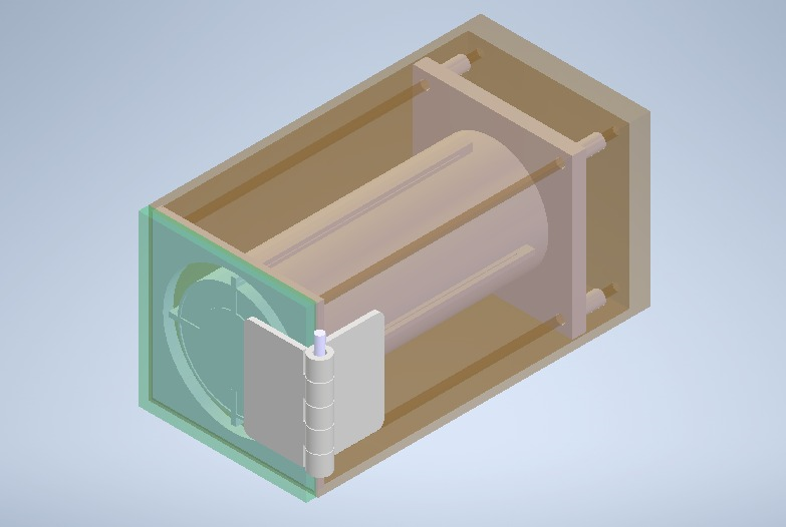
Antenna Deployment Mechanism Overview
The complete Automated Booming mechanism can be seen in the below video
Orbit and Orientation of Cube Satellite
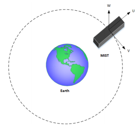
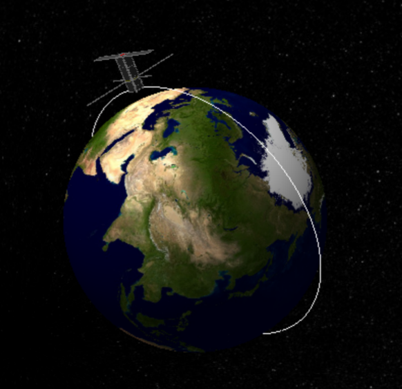
Generally, Cube Satellites are placed in an orbit which is 600 – 700 km above Sea level. The direction of travel along the orbit is in the X direction.The orientation and direction of travel of the Cube Satellite help determine which face of the satellite experiences maximum and minimum solar exposure.
Different Types of Radiations Experienced in Space
Radiation in space refers to the emission and transmission of energy in the form of electromagnetic waves or particles.There are different types of Radiations and they are as follows:
Solar Radiation
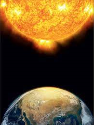
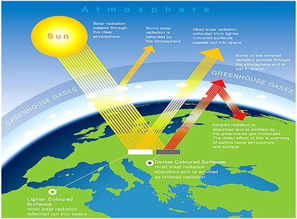
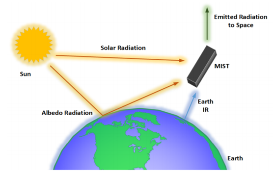
- The radiation from the sun is the major source of heating that occurs on a satellite. The intensity of solar radiation varies; this is due to the elliptical nature of the Earth's orbit.
- The Heat transfer is given by the equation:
\[ \dot{Q}_{A1,\text{solar}} = (\alpha A1)(S_{\text{solar}})(A_{A1}) \]
Earth Infrared Radiations
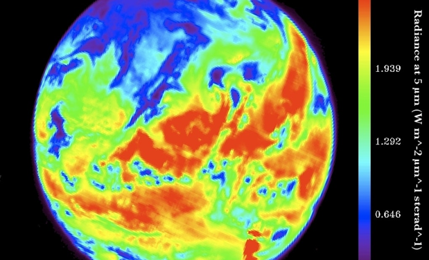
- The radiation from the sun is absorbed by the earth and eventually emitted as Infrared Radiations. The intensity of this radiation is greater in warmer areas as shown in the figure.
Albedo Radiation
- Sunlight reflecting off a planet's surface is known as Albedo Radiation. The effect of this radiation is profound over continents as land masses reflect more light than water bodies. The average Albedo radiation is 30% of the solar radiation.
Radiative Heat Transfer Experienced by the Cube Satellite
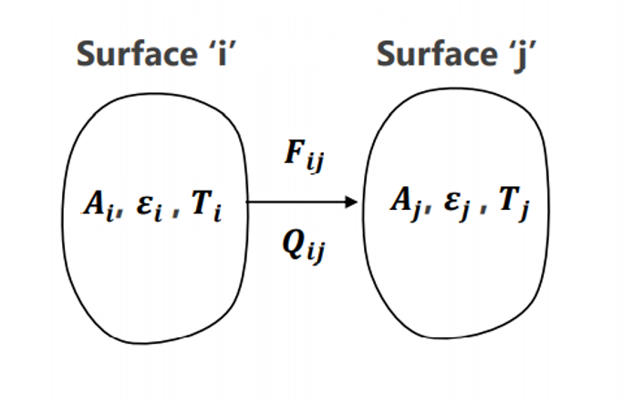
- The satellite experiences radiative heat transfer due to these different radiations. The general expression for radiative heat transfer is shown below:
- \[ Q_{ij} = A_i \varepsilon_i F_{ij} \sigma (T_i^4 - T_j^4) \]
where:
- A = Surface area.
- \( \varepsilon \) = Emissivity of the surface, which determines the amount of thermal radiation emitted.
- \( F_{ij} \) = View factor between the surfaces, defined as the fraction of total radiant energy that leaves surface 'i' and arrives directly on surface 'j'.
- \( \sigma \) = Stefan-Boltzmann constant (\( 5.67 \times 10^{-8} \) W/m² K⁴).
- \( T_i, T_j \) = Surface temperatures in absolute units (K).
By considering all these factors a thermal analysis of the cube sat was done and inorder to with-stand the thermal loads Aluminium 2024 an alloy of Aluminium was used to build the cube Sat
Main Components
- Antenna Hub Material-Aluminium 2024
- Base Material-Aluminium 2024
- Lid Material-Aluminium 2024
- Torsion Spring Material-Beryllium Copper
- Compression Springs Material-Beryllium Copper
- Hinge and pin assembly Material-Beryllium Copper
- RF Plates
- Columns Material-Aluminium 2024
Design of Various componets of the Autonomous Booming Mechanism
The below section deals with the design and development of the main components of the antenna booming mechanism.It also tells all the design related constrains taken into consideration
Design of Box and Lid
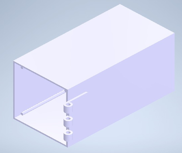
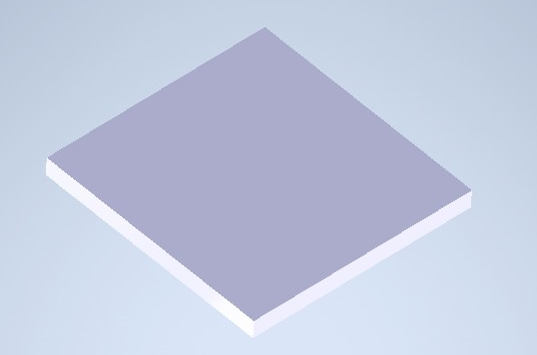
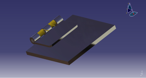
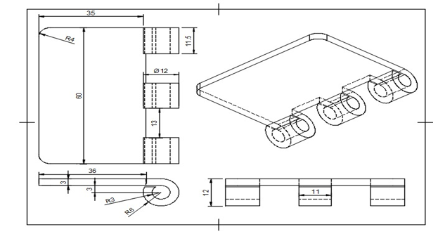
Design of Hinges
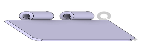
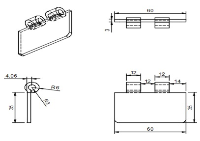
Hinges are used to couple the lid to the box by means of a revolute joint. The design of hinges can be divided into two types, male, and female hinges. The male hinge is mated to the box while the female hinge is mated to the lid. The male and female hinges are, themselves, couple using a hinge pin. The pin allows the two hinges to rotate about a common axis and ensures smooth movement of the lid. The motion of these hinges is actuated by means of a torsion spring. The hinges are made of Beryllium-Copper.
Design of Torsion Springs
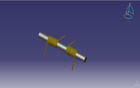
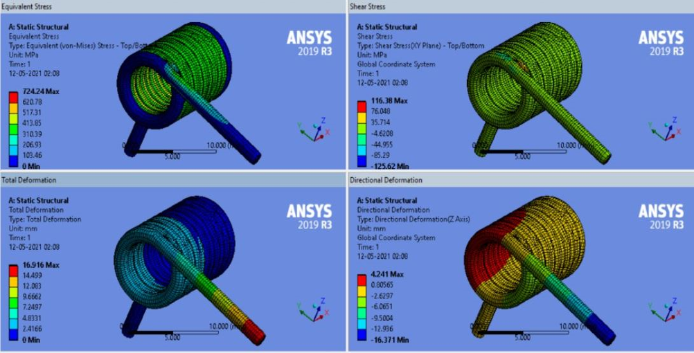
The torsion spring has a spring index of 7 in order to make it easier to manufacture. It has a wire diameter of 1.016 mm and a mean diameter of 7.112 mm. It has an internal diameter of 6.096 mm and therefore can easily fit around the pin of diameter 5 mm with a clearance of about 0.5 mm. This ensures reduced contact between hinge pin and torsion spring and therefore results in smoother operation of the lid assembly as a whole and also increases the operational life of the torsion spring. The angle traversed by lid from closed to open position is 270o. This results in a total deflection of 16.75 mm. Furthermore, it has been calculated to provide a torque of 131.308 N-mm and possesses a stiffness of 0.0278 Nm / rad.
Calculations for Design of Torsion Spring
The inner diameter of the spring was assumed to be greater than or equal to 6 mm so that there would be a clearance of at least 0.5 mm between the spring and hinge pin when assembled. Also, the length is assumed to be 12 mm for the spring to fit between the hinges on the pin.
The material Beryllium-Copper was assumed to be isotropic and possessing uniform density.
- d = Wire diameter of Spring (mm)
- D = Mean diameter of Spring (mm)
- Di = Inner diameter of the spring (mm)
- Spring Index = C = 7
- Length of Spring = L = 12 mm
- Di ≥ 6
- C = D/d
- Di = D - d
- Angle of Rotation (\( \theta \)) = \( \frac{3\pi}{2} \) rad
- Young’s Modulus (E) = 131 GPa
$D = 7 \times 1.016 = 7.112$
Moment of Inertia (I) = $\frac{\pi d^4}{64} = \frac{\pi \times 1.016^4}{64} = 0.0523 \, \text{mm}^4$
Number of Active Turns (i) = $\frac{L}{d} = \frac{12}{1.016} \approx 11$
Angle of Rotation ($\theta$) = $\frac{3\pi}{2} \, \text{radian} = 3.14 \, \text{radian}$
Young's Modulus (E) = 131 GPa
Total Deformation (y) = $\frac{\theta \times D^2}{2} = \frac{3.14 \times 7.112^2}{2} = 16.75 \, \text{mm}$
$y = \frac{Mt}{\pi \times D_i \times D}$
Torque (Mt) = $\frac{16.75 \times 2 \times 13000.38 \times 0.0523}{7.112^2 \times 11 \times \pi} = 131.38 \, \text{N-mm}$
Stiffness (K) = $\frac{Mt}{\theta} = 27.864 \, \text{N-mm}^{-1}$
Radius (r) = 0.0278 N-mm$^{-1}$
Thus, the designed torsion spring possesses a stiffness of 0.0278 N-m/rad and transmits a torque of 0.1318 N-mm.
Design of Antenna Hub & RF Plates
The below section deals with the detailed design of the Antenna Hub and RF Plates
Antenna Hub
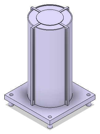
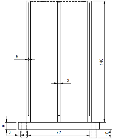
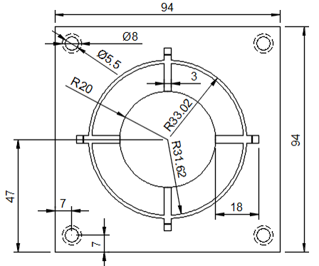
It is a 140 mm long cylindrical part with radially aligned slits on its periphery. It also consists of a 94 X 94 mm Base plate that is 8 mm thick with 10 mm protrusions that are used to guide its motion on smooth rods. The main function is to carry the RF plates outside the box. It is made of Aluminium
RF Plates
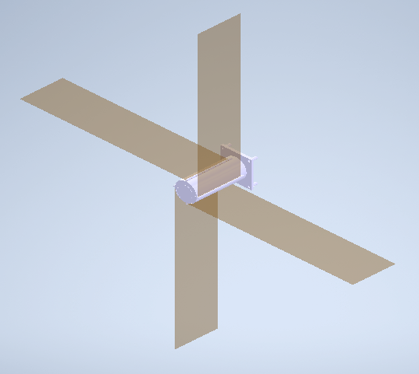
They are 13 X 51 cm fitted in the hub and tethered around it. It is used for data transmission to and from the satellite. It is made of Beryllium-Copper.
Design Of Compression Spring
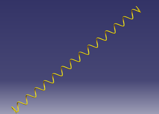
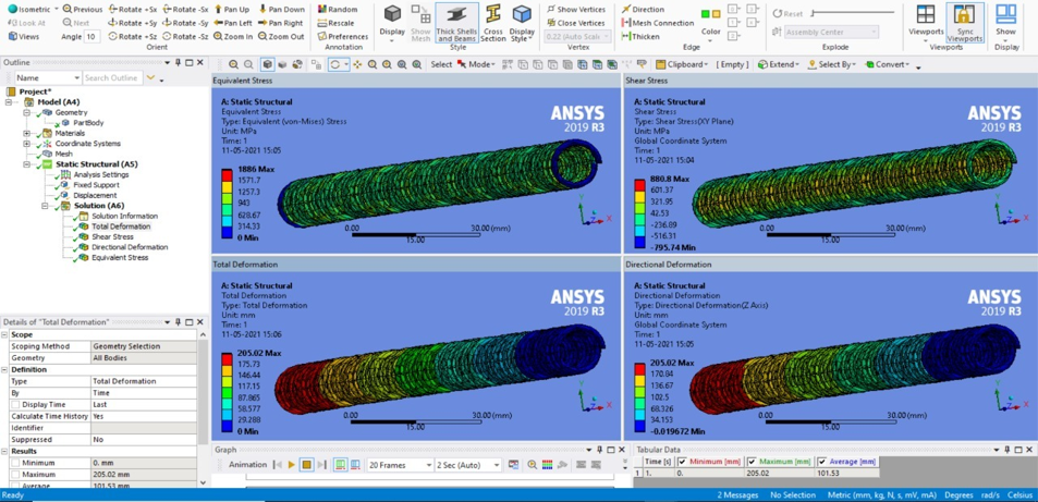
Compression Springs are used to push the antenna hub out of the box. It is a spring of length of 230 mm that is loaded to 25 mm and has a maximum extension of 205 mm. A spring index of 7 is used as it is easy to manufacture. It has a mean diameter of 10.493 mm. FEA analysis is then conducted to yield a max. shear stress of 880.8 N/〖𝒎𝒎〗^𝟐 and results in a stiffness of 506.2 N/mm.
Calculation of Design of Compression Spring
- d = Wire diameter of Spring (mm)
- D = Mean diameter of Spring (mm)
- Di = Inner diameter of the spring (mm)
- Spring Index = C = 7
- Length of Spring without compression = L = 230 mm
- Length of Spring after compression = 25 mm
- Total spring deflection (\( y \)) = 230 - 25 = 205 mm
- Force (\( F \)) = FOS × Wt. of Hub = 2 × 19.62 = 39.24 N
- Di ≥ 4.5
- C = D/d
- Di = D - d
\( D = 7 \times 1.499 = 10.493 \, \text{mm} \)
\( K = \frac{{4C-1}}{{4C-4}} + 0.651C = \frac{{(4 \times 7)-1}}{{(4 \times 7)-4}} + 0.651 \times 7 = 1.218 \)
\( \text{Outer Diameter} \, (D_o) = D + d = 10.493 + 1.499 = 11.992 \, \text{mm} \)
\( \text{Inner Diameter} \, (D_i) = D - d = 10.493 - 1.499 = 8.99 \, \text{mm} \)
\( \text{Modulus of Rigidity} \, (G) = 4.4 \times 10^4 \, \text{MPa} \, (\text{Beryllium-Copper}) \)
\( y = \frac{{8FD}}{{3i}} \left( \frac{{d^4G}}{{4C}} \right) = 205 \, \text{mm} \)
\( \text{Number of active turns} \, (i) = \frac{{205 \times 1.499}}{{4 \times 39.24 \times 10.493}} = 125.57 \approx 126 \)
\( i' = i + n = 126 + 2 = 128 \, (n = 2 \, \text{for square, ground ended}) \)
\( \text{Max. Deflection} \, (y_{\text{max}}) = \frac{{8FD}}{{3i}} \left( \frac{{d^4G}}{{4C}} \right) = 205.69 \, \text{mm} \)
\( a = 0.25y_{\text{max}} = 0.25 \times 205.69 = 51.424 \, \text{mm} \)
\( \text{Solid Length} = i' d = 128 \times 1.499 = 191.872 \, \text{mm} \)
\( l_o \geq (i + n)d + y_{\text{max}} + a = (128) \times 1.499 + 205.69 + 51.424 = 448.982 \, \text{mm} \)
\( \text{Pitch} \, (p) = \frac{{l_o - 2d}}{{i'}} = \frac{{448.98-(2 \times 1.499)}}{{128}} = 3.4825 \, \text{mm} \)
\( 8FDK \left( \frac{{\pi D^3}}{{16C}} \right) = 880.8 \, \text{MPa} \)
\( F = \frac{{\pi \times 1.499^3 \times 880.8}}{{8 \times 10.493 \times 1.218}} = 91.15 \, \text{N} \)
\( \text{Required Stiffness} \, (k_o) = \frac{{F}}{{y}} = \frac{{91.15}}{{205}} = 444.63 \, \text{N/mm} \)
\( \text{Actual Stiffness} \, (k_a) = \frac{{d}}{{4G}} \left( \frac{{8iD^3}}{{4C}} \right) = \frac{{1.499 \times 4.4 \times 10^4}}{{8 \times 126 \times 10.493^3}} = 437.026 \, \text{N/mm} \)
Design of Blocking Part
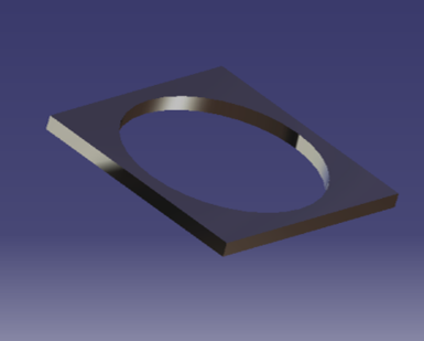
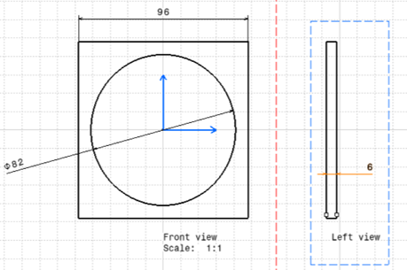
The blocking part is a square plate with a side length of 96mm and 6mm thickness. A hole of 82mm diameter is blanked into it. The material used to construct the blocking part is aluminum as it is strong light and robust. Function-To prevent the antenna hub from flying away to outer space.
Design Of Locking Mechanism
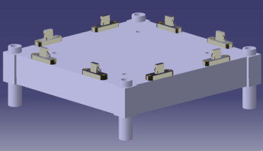
The Function is to lock the antenna hub in a fixed place and helps in the smooth transmission and receiving of signals There are two components which constitute the locking mechanism they are the male locks and the female locks
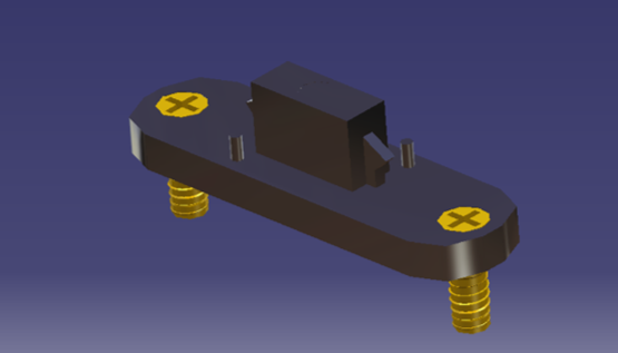
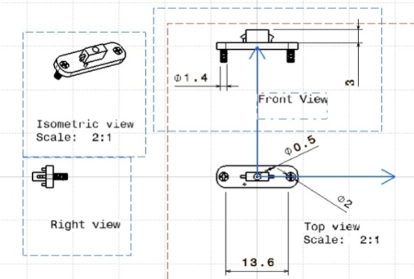
Male Locking Part
The male locking part is made of Aluminum The male locking parts have guide pins and protrusions which are essential for the locking mechanism to work
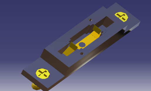
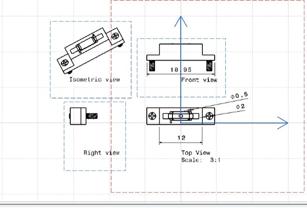
Female Locking Part
The outer body of the female lock is made of Aluminum but the flexible sheet present inside the female lock is made of Beryllium-Copper The female locks have guide holes and a flexible plates which are essential for the snapping action to take place
Assembly of Locks
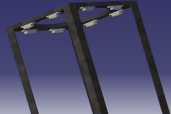
The 8 female locks are attached to the bottom part of the blocking part.The 8 male locks are attached to the base of the antenna hub
Working Of Locking Mechanism
There are 8 pairs of male and female locks which constitute the complete locking mechanism.The force on the blocking part is divided between these 8 pair of locks
Kinematic Analysis
Kinematic analysis is conducted to evaluate the diverse forces exerted on the components of the CubeSat.
Kinematic analysis of the Lid
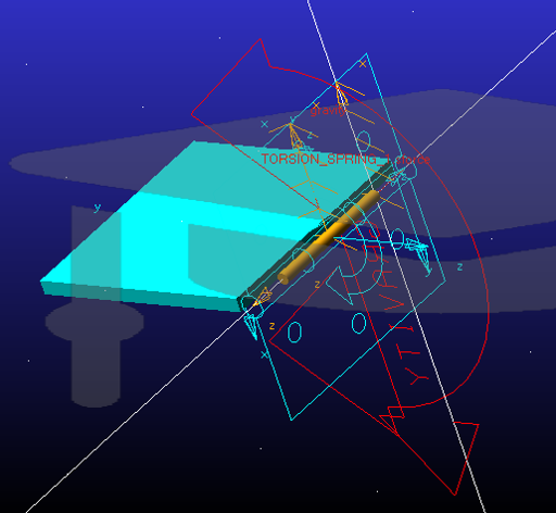
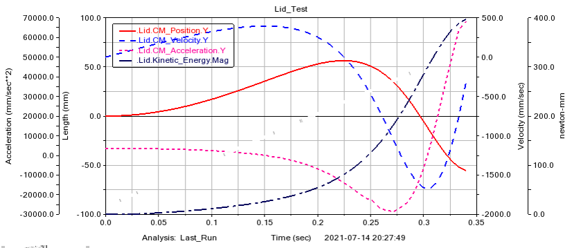
This simulation consists of two bodies Lid and Pin (which is grounded). A revolute joint is added between Lid and Pin. Earth normal gravity is assumed to act in –Y direction. A torsion spring of 27.864 Nmm/rad is added coaxially around the pin and connected to the lid. Angle at pre-load is set to 3π/2. The mass of the lid is determined automatically in accordance with the geometry and material (Aluminum) of the lid.
Kinematic Analysis of Antenna Hub
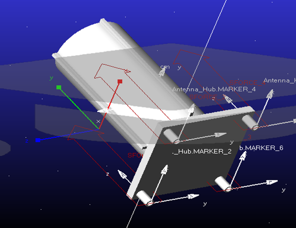
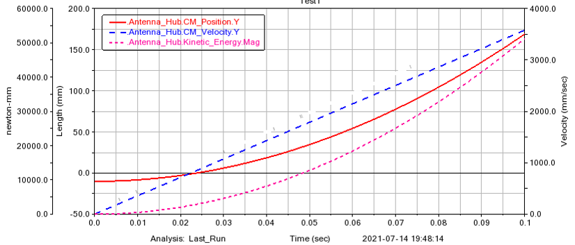
The kinematic analysis was conducted on Adams v2021.1 student edition. A force of 91.15 N is applied to each of the cylindrical protrusions below the base plate in +Y direction. Earth normal gravity is assumed to act in –Y direction. The total mass of the antenna hub along with RF plates is considered to be 8 kg.
Dynamic Analysis of Spring Forces
The dynamic analysis of spring force consists of the analysis of both torsion and compression springs
Torsional Spring Equations
.png)
$Lenght \ (L) = 100 \ mm = 0.1 \ m$
$Breadth \ (b) = 99 \ mm = 0.099 \ m$
$Distance \ from \ center \ of \ lid \ to \ hinge \ axis \ (e) = 56.405 \ mm = 0.056405 \ m$
$Mass \ of \ Lid \ (M) = 160.38 \ g = 0.16038 \ kg$
$Mass \ per \ unit \ length \ of \ the \ lid \ (M/L) = \frac{{0.16038}}{{0.1}} \ kg/m$
$Stiffness \ of \ Torsion \ Spring = 0.027864 \ N/m$
$Moment \ of \ Inertia \ of \ lid \ about \ hinge \ axis \ (I) = \frac{{0.16038 \times 0.1^2}}{{12}} + \frac{{0.16038 \times 0.099^2}}{{12}} + \frac{{0.16038 \times 0.056405^2}}{{12}} = 6.8521 \times 10^{-4} \ kgm^2$
$Torque \ on \ Lid \ (\tau) = \int_0^{0.1} \frac{{0.16038 \times x \, dx}}{{0.099}} = 0.0778 \ Nm$
Consider the general equation of motion for a torsion spring:
$I\theta'' + k\theta = 0$
Consider a general solution:
$\theta = A \sin(\omega t) + B \cos(\omega t)$
$\theta' = A \omega \cos(\omega t) - B \omega \sin(\omega t)$
$\theta'' = -\omega^2 (A \sin(\omega t) + B \cos(\omega t))$
Substitute the solution in the equation of motion:
$I(-\omega^2 (A \sin(\omega t) + B \cos(\omega t))) + k(A \sin(\omega t) + B \cos(\omega t)) = 0$
$\omega^2 = \frac{{k}}{{I}} = \sqrt{\frac{{0.027864}}{{6.852 \times 10^{-4}}}} = 9.018 \, rad/s$
Substitute $\theta = \frac{{3\pi}}{{2}}$; $\theta' = 0$; $t = 0$:
$\frac{{3\pi}}{{2}} = A(0) + B(1)$
$B = \frac{{3\pi}}{{2}}$
Substitute $\theta = 0$; $B = \frac{{3\pi}}{{2}}$:
$\frac{{3\pi}}{{2}} = A(\omega) - \frac{{3\pi}}{{2}}(0)$
$A = 0$
Substitute the results in $\theta = B \cos(\omega t)$:
$\theta = \frac{{3\pi}}{{2}} \cos(9.018 t)$
Put $\theta = 0$; $B = \frac{{3\pi}}{{2}}$:
$\frac{{3\pi}}{{2}} = \frac{{3\pi}}{{2}} \cos(9.018 t)$
$\omega t = \frac{{\pi}}{{2}}$
$t = \frac{{\pi}}{{2\omega}} = \frac{{\pi}}{{2}} \times 9.018 = 0.1741 \, s$
Substitute the value of $t$ and $\omega$ in $\theta' = -3\pi \omega \sin(\omega t)$:
$\theta' = -3\pi \times 9.018 \sin(9.018 \times 0.174) = -42.49 \, rad/s$
$\theta'' = -9.018^2 \times 3\pi \cos(9.018 \times 0.174) = -0.2922 \, rad/s^2$
Compression Spring Equations
$\tau = 880.79 = \frac{{8FDk}}{{\pi D^3}} \Rightarrow F = \frac{{880.79 \times \pi \times 1.499^3}}{{8 \times 10.433 \times 1.218}} = 91.157 \, N$
$K = \frac{{F}}{{y}} = \frac{{91.15}}{{205}} = 444.63 \, N/m$
Using the second order differential equation governing spring forces:
$m \frac{{d^2m}}{{dx^2}} + c \frac{{dm}}{{dx}} + kx = 0$
Assuming a negligible damping condition:
$m \frac{{d^2m}}{{dx^2}} + kx = 0$
$x = a \cos(\omega t) + b \sin(\omega t)$
$\frac{{dx}}{{dt}} = -\omega(a \sin(\omega t) - b \cos(\omega t))$
$\frac{{d^2x}}{{dx^2}} = -\omega^2(a \cos(\omega t) + b \sin(\omega t))$
$\omega = \sqrt{\frac{{k}}{{m}}} = \sqrt{\frac{{4 \times 444.63}}{{8}}} = 14.91 \, rad/s$
Applying boundary conditions of $x = 0.205 \, m$ at $t = 0 \, s$, and $v = 0 \, m/s$ at $t = 0 \, s$:
$a = 0.205 \, m$; $b = 0 \, m$
At 25% of maximum compression:
$0.051 = 0.205 \cos(14.91t) \Rightarrow t = 0.0884 \, s$
Therefore, the spring takes 0.0884 seconds to reach 25% of maximum compression. At that instant:
$a = \frac{{d^2x}}{{dt^2}} = 11.39 \, m/s^2$
Therefore force on the blocking plate, $F = m \times a = 8 \times 11.39 = 91.12 \, N$
Force on each blocking part, $F_{each} = \frac{{91.12}}{{8}} = 11.39 \, N$
To find the velocity of the spring when complete deformation occurs:
$\frac{{1}}{{2}} kx^2 = \frac{{1}}{{2}} m v^2 \Rightarrow v = \sqrt{\frac{{444.63 \times 0.205^2}}{{8}}} = 1.528 \, m/s$
Angular velocity, $\omega = 42.49 \, rad/s \Rightarrow v = \omega R = 42.49 \times 0.1 = 4.249 \, m/s$
Angular acceleration, $\alpha = 0.2922 \, rad/s^2 \Rightarrow a = \alpha R = 0.02922 \, m/s^2$
Impulse Force Calculation
.png)
To find the impulse force on the box, consider:
If the hinge axis is the left edge of the lid depicted:
$P = \int_0^{10} v \, dm$, where $v = \dot{\theta} x$
$P = \int_0^{10} \dot{\theta} x \rho \, dx \cdot t$
$P = \rho t \dot{\theta} \int_0^{10} x \, dx$
$P = \rho t \dot{\theta} \left[\frac{{x^2}}{2}\right]_0^{10}$
$P = 2700 \times 6 \times \frac{{42.49^2}}{{2}} \times 10^{-4}$
Therefore, $P = 5.162 \, kgm/s^2$
Hence, the impulsive force acting on the box is 5.162 N.
It is assumed that the impulsive force lasts for 0.5 seconds.
Therefore, $\Delta t = 0.5 \, sec$
We know that $F = \frac{{P}}{{\Delta t}}$
Hence, $F = \frac{{5.162}}{{0.5}} = 10.324 \, N$
Finite Element Analysis of Various Components of the Cube Sat
FEA was done on Aluminium 2024 and Beryllium-Copper
FEA of the Lid
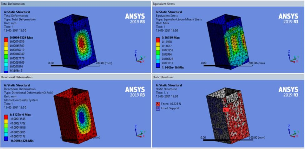
The lid and the box undergo a collision due to which an impulsive force of 10.324 N acts on it for a time interval of 0.5 sec. The lid has to be tested for this force because it must have the ability to withstand this force. In order to analyze the lid first, the fixed supports had to be inserted. Fixed support indicate to the system that the force won’t be experienced at that location. The hinge axis and the edges of the hinge were considered as the fixed supports and a force of 10.324 N was applied on the plane surface of the lid and the following results were obtained as shown in the figures.
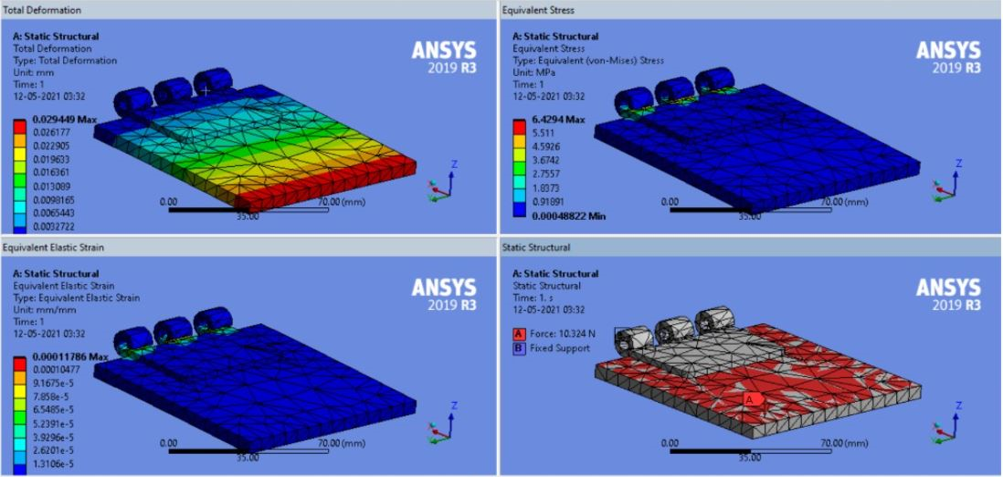
The above image shows the total deformation, equivalent stress and strain and the application of force. The max values of the equivalent stress are 6.429 MPa. This shows that the design is safe. The compressive yield strength of Aluminium is 280 MPa. If we take a factor of safety of 0.5, the max stress the material can experience is 140 MPa and the obtained value is well below it.
FEA of the Pin
The pin is a part of the hinge, the hinge on the whole experiences a torque of 131 N-mm because of the torsional loading of the torsion springs. These values are taken from the torsion spring calculations. As the hinge experiences all its force on its pin (except during loading of the torsion spring), it is sufficient to analyze the pin of the Hinges, this saves compilation time while maintaining design safety. The pin must be able to handle the applied torque. The FEA is done on the pin by taking a torque of 131 N-mm acting on it. While applying this force the two top surfaces of the cylindrical pin are fixed.
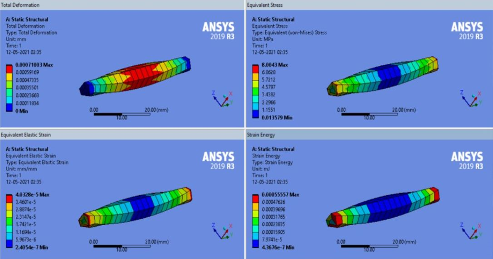
When a torque of 131 N-mm acts on the pin the equivalent stress developed is 8.0043 MPa, the yield strength of Aluminium is 280 MPa. Taking a factor of safety of 0.5, the max allowable stress is 140 MPa therefore the designs are safe.
FEA of the Box
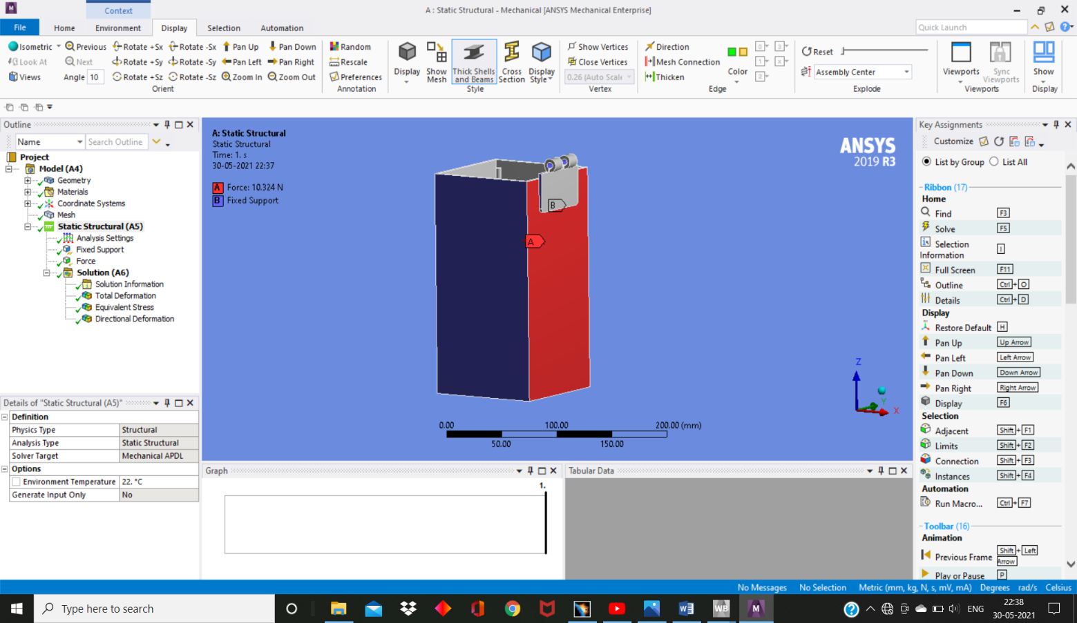
The lid hits the box and an impulsive force of 10.324 N is generated and the designs of the box are checked for these forces as this is the max force acting on it. The other walls of the box and the edges of the hinges are considered as hinge supports. The below figure shows the fixed supports and the application of force.
The image shows the FEA of the box made of Aluminium. The deformation is of the order 10-6. This shows that the effect of the impulsive force on the box is miniscule.Aluminium 2024 can withstand the stress induced on the box
FEA of the Antenna Hub
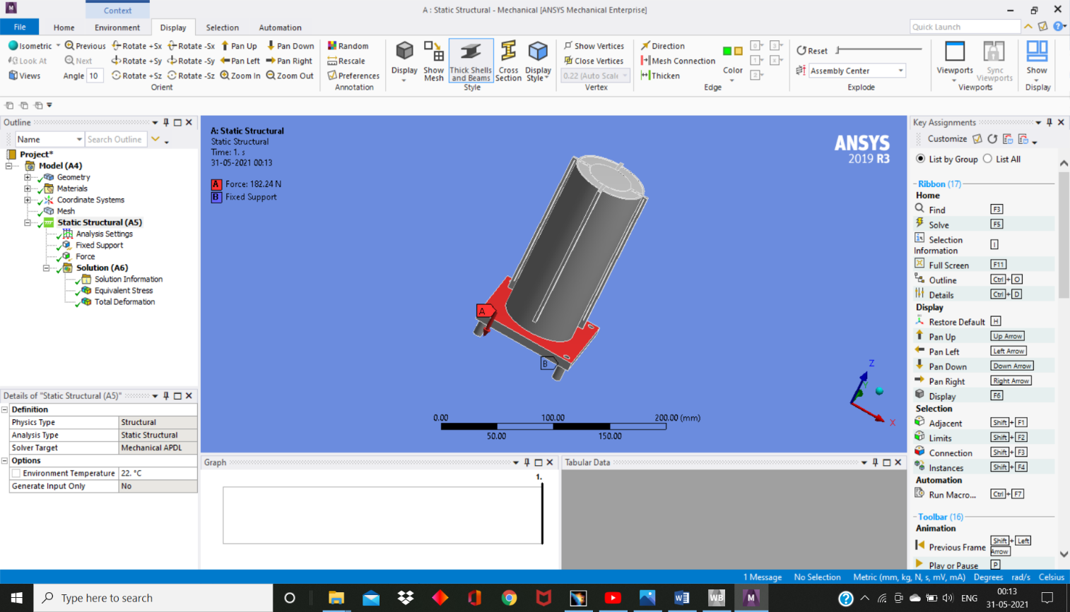
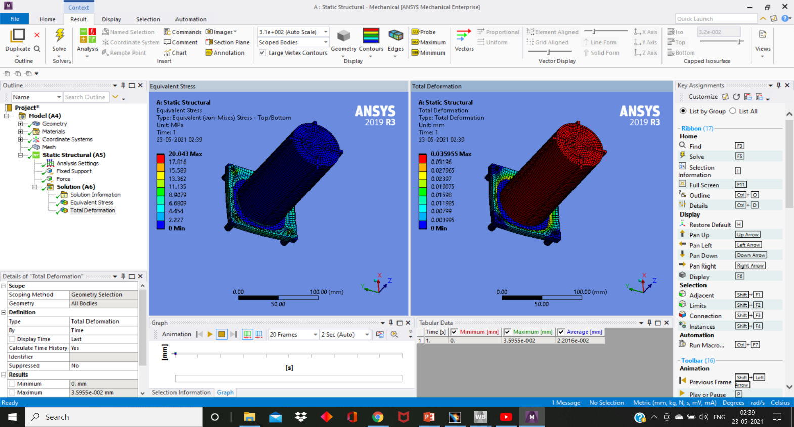
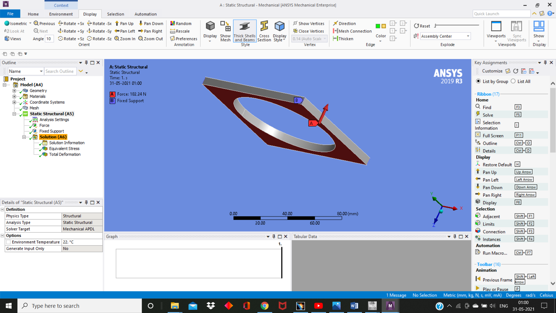
From the physical calculations it can be seen that the force acting on the antenna hub is in the downward direction and has a magnitude of 91.12 N. For safety considerations the analysis is done by applying a force twice the magnitude. The supporting structures for the springs are considered as fixed supports and the force of 182.24 N is applied to the top surface of the base. The below figure shows the application of forces and supports.
From the image it can be seen that the base of the antenna hub experiences a significant amount of stress and the antenna hub undergoes maximum deflection. The value of the stress is of the order 20 MPa as shown in the figure but the safe working stress is of the order 140 MPa, and therefore ensures safety.
FEA of the Blocking Part
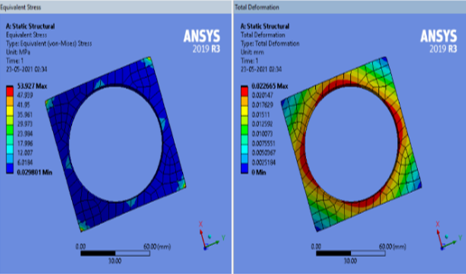
As mentioned earlier, a blocking part is used to prevent the antenna hub from ejection to outer space. Therefore, it experiences the same force of 91.12 N but in the opposite direction. FEA is done by applying a force twice the magnitude of the actual force, hence a force of 182.24 N is applied on the blocking part in the upward direction.
The figure shows the results for the analysis of the blocking part using Al. The value of the stresses is well under the safe stress conditions. In order to damp these forces RVT compounds are used. These compounds absorb the forces acting on the blocking part and prevent the forces dissipating to other components of the antenna deployment mechanism.
Analysis of Contact Regions
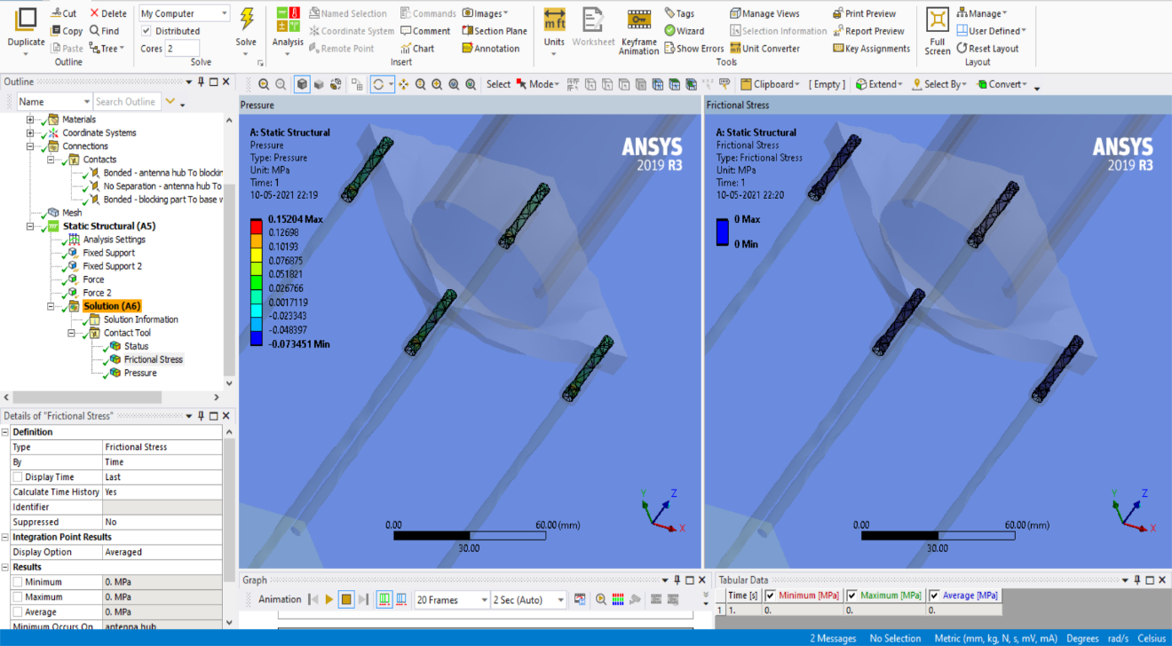
There are contact patches between the columns and the holes of the antenna hub. There are certain pressure stresses acting on them. The frictional stresses on the columns are zero because of the presence of DU Bushes. The following image show the pressure stresses between the columns and the holes of the antenna hub.
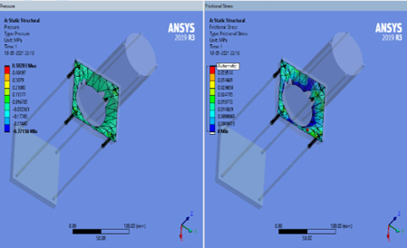
There are pressure stresses and frictional stresses developed when there is a collision between the base of the antenna hub and the blocking part. The below images shows the effect of these stresses between the contact region.
FEA of Locking Mechanism
There are eight pairs of male and female locks and each pair experiences 1/(8 ) th of the force experienced by the blocking part (the force experienced by the blocking part is divided between these eight locks). The FEA is done by applying a force of 11.39 N on both the male and female locks but the opposite direction. The application of the forces and support structures on the male and female locks are shown in the figure.
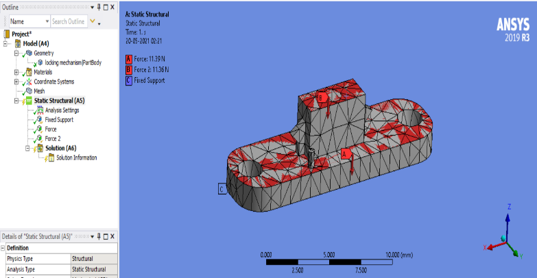
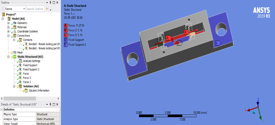
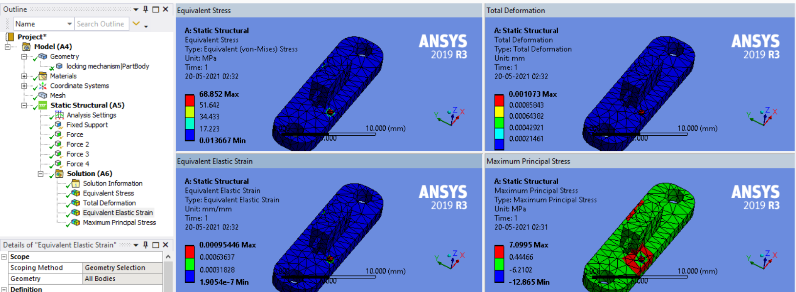
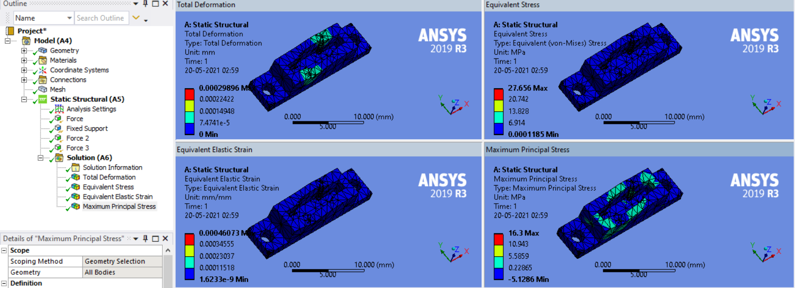
The locks are made of Aluminum 2024 because Steel isn’t strong enough to handle the stresses developed on these locks. These locks are very small so 11.39N is a significantly large force acting on these locks.
Fabrication of Antenna Deployment Mechanism
The material chosen to build the parts of the antenna deployment mechanism is Aluminum 2024. But before fabricating the parts with Aluminum 2024, a prototype was built to establish proof of concept, using PLA.FDM was used to print the model of the Antenna Deployment Mechanism using PLA material. FDM (Fused Deposition Modelling) falls under the material extrusion category of 3D printing technology. In an FDM printer, the filament is pushed into the hot extruder. The filament is heated first and then deposited through the nozzle onto a build platform in a layer-by-layer process to form the complete object.
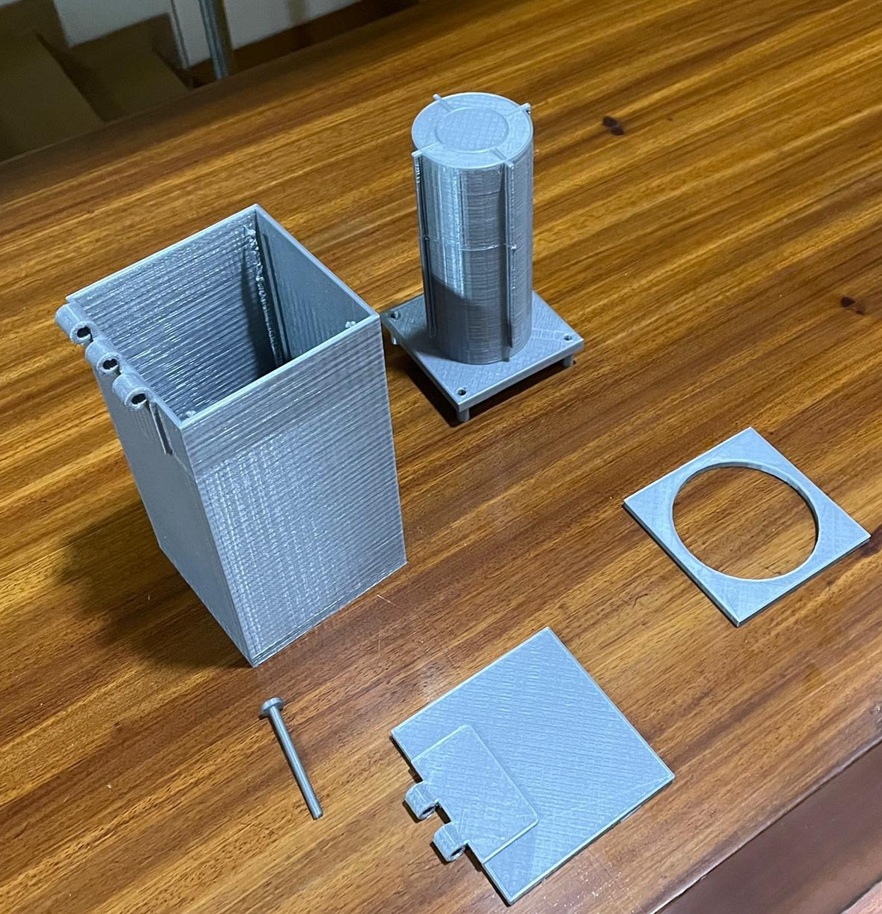
Result & Discussion
Initial objectives were met – conformity with 2u configuration, deployment of antenna and hub from cube-sat, static and dynamic stability of mechanism
Due to budget constraints, the model was 3D printed using PLA material rather than Aluminum and beryllium. The finite element method confirmed soundness of concept and design for both constructions.
Utility & Scope for Future Work
References
- Doncaster, B., et. al., “SpaceWorks’ 2017 Nano/Microsatellite Market Forecast”, Proceedings of the AIAA/USU Conference on Small Satellites, Swiftly Session 2, SSC17, 2017
- Adamowski, J., “SmallSat Market Forecast to Exceed $30 Billion in Coming Decade”, Space News, 9th, August 2017, Online
- Murphey, T. et. al., “High Strain Composites,” Proceedings of the 2nd AIAA Spacecraft Structures Conference, 2015 AIAA SciTech Conference, Session on Composite Materials for Spacecraft Structures, AIAA 2015-0942, Kissimmee, FL.
- Thermal Analysis and Control of MIST CubeSat
- Thermal Analysis of a 3U-Cubesat, a Case Study of Pakal Satellite.
- Annon, “Tubular Spacecraft Booms (Extendible, Reel Stored),” tech. Prep. SP-8065, NASA, Feb 1971
- Cox, K., et. al., “Flight Build of a Furled High Strain Composite Antenna for CubeSats,” Proceedings of the 5th AIAA Spacecraft Structures Conference, 2018 AIAA SciTech Conference, Session on Composite Materials for Spacecraft Structures, AIAA 2018-1678, Kissimmee, FL.
- Mechanism Design & Flight Build of Furled High Strain Composite Antenna for CubeSats Bruce Davis*, Ryan VanHalle*, Kevin Cox* and Will Francis* AIAA SciTech Forum 8-12 Jan 2018